

The fitting geometry decides whether turning alone is enough
A straight hydraulic adapter may be dominated by concentric diameters, internal bores, threads and a sealing cone. A connector body with a radial port, cross hole or off-center passage adds a second machining direction. A hose fitting with wrench flats adds a polygon feature. Before comparing machines, divide the drawing into axial turning features, radial drilling or milling features, and flats or polygons. This immediately narrows the choice between a gang-tool CNC lathe, a turn-mill center and a dedicated polygon-milling machine.
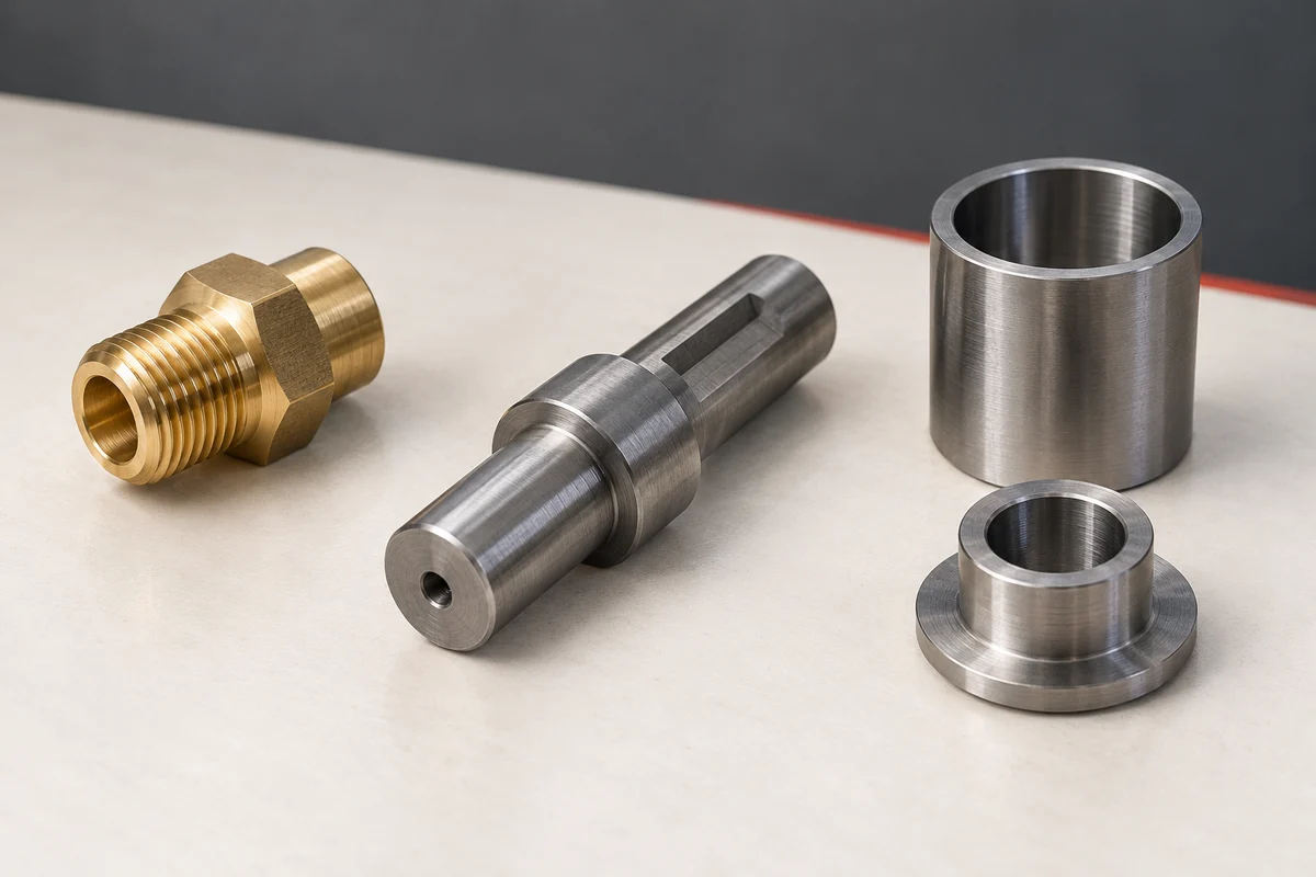
Straight threaded fittings favor a compact gang-tool route
When the part is produced from bar and most features are concentric, gang tooling provides a direct route for outside turning, boring, drilling, threading and cut-off. The GDM-T40-360 offers 40 mm bar capacity, 370 mm machining length and a hydraulic 40 collet. The GDM-46A adds a 49 mm spindle bore and machining lengths up to 400 mm. For a straight threaded adapter, compare the blank and finished drawing with these published ranges, then confirm the workholding and tool clearance.

Cross holes and side ports point toward turn-mill machining
A side port can force a second setup if the machine only turns along the spindle axis. The GDM-CX-Y55 combines X/Y/Z-axis motion with radial and axial live-tool heads for turning, milling, drilling and tapping. Its published application scope includes valve parts and components with cross-hole, off-center or compound features, with bar capacity up to 45 mm and spindle speeds up to 5,000 rpm. For a hydraulic connector body that needs a thread, sealing face and radial hole, this is the kind of capability that may reduce part transfers; the drawing must still confirm feature position, tool access and deburring requirements.
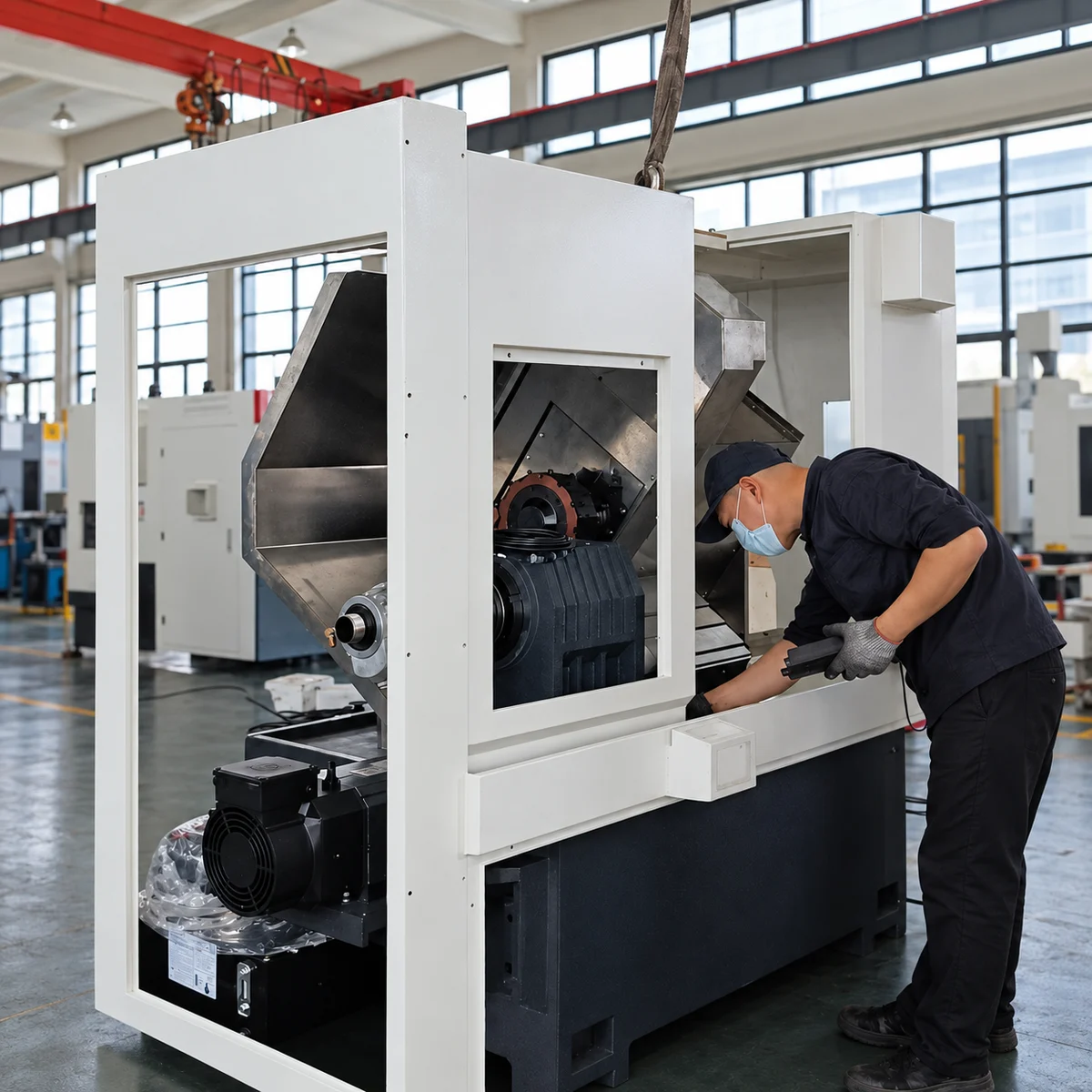
Does a slant bed lathe with live tools need a Y axis for this fitting?
Live tooling rotates a cutting tool for operations such as drilling or milling; it is a separate configuration question from the bed layout. An off-center hole or flat also raises questions about axis travel, spindle positioning and tool approach. Do not infer a Y axis, a sub-spindle or a particular axis count from the words turn-mill alone. GDM-CX80-650W has a published BMT40 live-tool turret for shaft and bar components. GDM-CX-Y55 has published X/Y/Z motion with radial and axial live-tool heads for chucking parts. Compare the actual port positions and clamping envelope with each configuration, then ask which features can be completed before the part must be regripped.
Wrench flats can be integrated or machined as a dedicated operation
Many hydraulic adapters use two flats or a hexagon for assembly. The GDM-HZ40-400 combines general turning with a powered fly-cutter head for two-flat, square, hexagonal and octagonal profiles, plus drilling and tapping, with bar capacity up to 40 mm. If the business mainly produces polygonal parts, the GDM-XF60 is a dedicated option for wrench flats, bolt and nut profiles, valve parts and tool shanks. Compare the required turning and polygon features with each proposed setup: which operations can be combined, and which would remain a separate polygon-machining step?
Seal faces and internal passages shape the process plan
Machine capacity is only one part of fitting production. Mark the thread form, sealing cone or face, O-ring groove, internal passage, cross-hole intersection and burr-sensitive edges. State whether the stock is brass, stainless steel or another specified material, and identify the dimensions that control sealing or assembly. Inspection may include thread gauges, concentricity checks, surface-finish requirements and verification that intersecting passages are clear. These requirements belong in the inquiry because they influence tool choice and operation sequence even when the outside diameter is unchanged.
Choose from the drawing, not from the industry name
For a useful machine recommendation, send the part drawing, material, stock diameter, finished length, thread and sealing standards, side-port locations, across-flats size, batch quantity and current process route. A simple straight adapter, a cross-drilled connector and a hex fitting may belong to the same industry but require different machines. Review the related valve-fitting guide when the parts also include appearance surfaces or valve-body features, or compare all published GEDEMA models before starting the inquiry.