

1. Separate the blank from the finished part
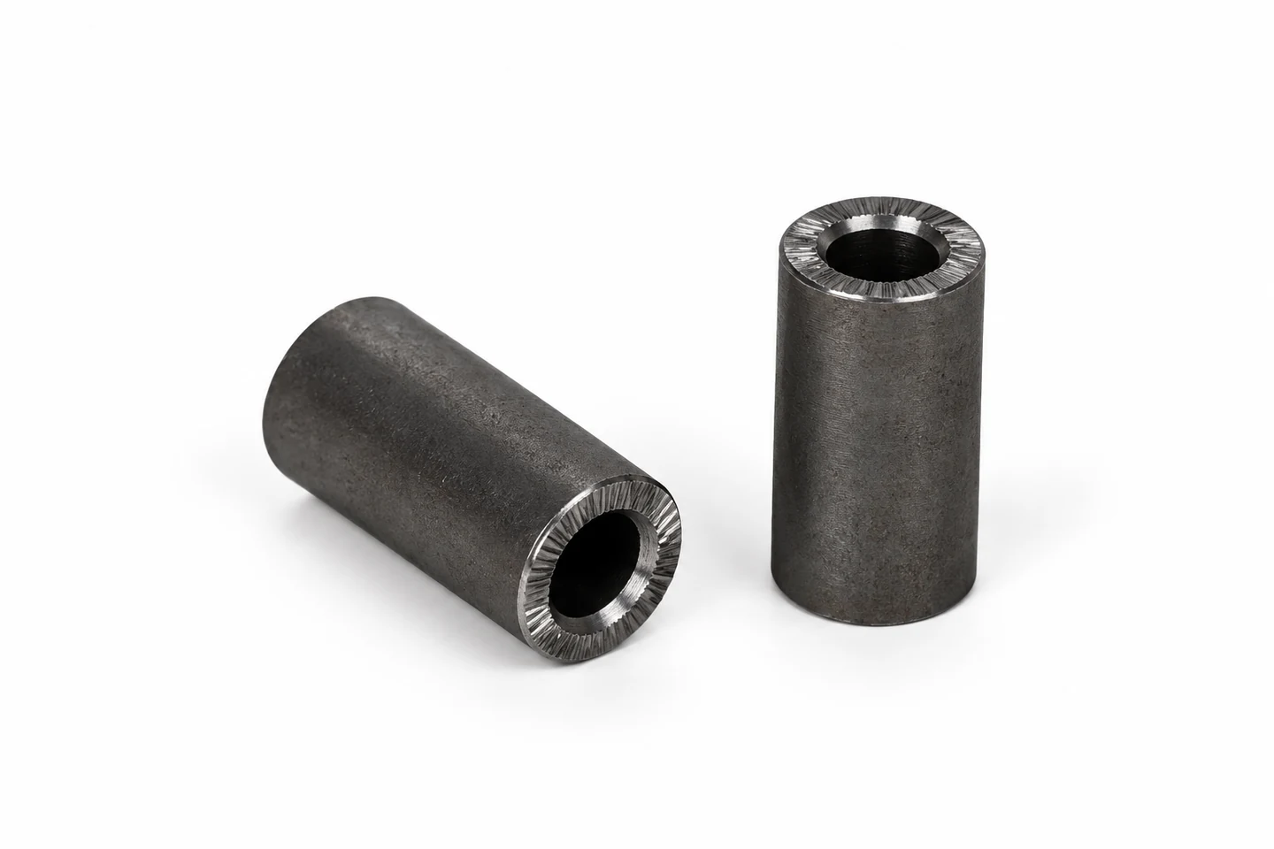
The two hollow cylinders below are sleeve blanks: they show a bore, rough outside surfaces and cut ends, rather than a fully defined finished component. A buyer should specify the starting outside diameter, bore, length and machining allowance separately from the finished dimensions. The blank determines what can be gripped and where material must be removed; the finished drawing defines the accepted result. Its material grade, heat treatment and intended use cannot be identified reliably from its colour. The part images in this guide have received AI-assisted retouching. Use them to describe shapes; use controlled drawings and inspection records for geometry, finish and accuracy. A common sleeve blank does not establish that every machine can complete every subsequent operation.

2. Sleeves, bushings, rings and discs: start with the turned profile
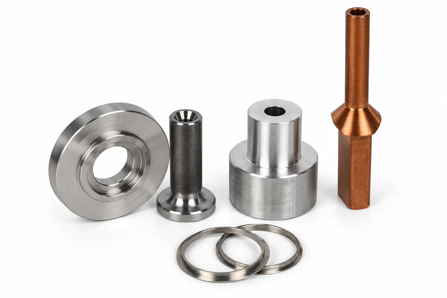
A sleeve or bushing combines an outside diameter with an internal bore. Rings and discs bring attention to face width, shoulders and the relationship between the bore and outside diameter. In the next group, most visible surfaces are rotational, making GDM-T40-360B a useful starting point for small-part turning discussions. Its published gang-tool layout belongs in a comparison of the required turning, drilling and tapping sequence. Show which face can be used for gripping, whether the part needs reversal, and which thin sections could be affected by clamping. The hexagonal section on one sample is a separate feature: the image does not establish that the gang-tool lathe cuts those flats. Mark whether it comes from the starting stock or needs an additional operation.
3. Shafts and stepped parts: check the working length and support
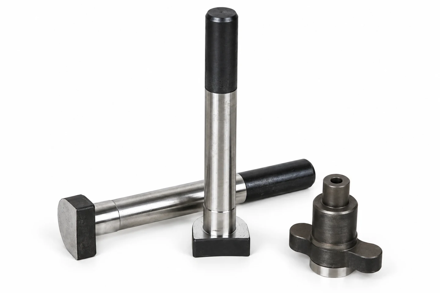
Shaft-type work is defined by the cylindrical sections, shoulders, grooves and end features that must be machined. The pictured shafts also retain non-round end sections; those should not be treated as proof of a milling operation on a turning-only machine. GDM-T80-350W is a starting point for this part group and is published as a compact hydraulic-servo-turret CNC lathe for shaft and chucking work. Before selecting it, distinguish total blank length from the section to be cut, then review the gripping length, free projection and access to each end. A long-looking photograph supplies no scale. If a shaft needs more working length or a particular support arrangement, compare another published model rather than assuming the photographed part fits the compact machine unchanged.
4. Flanges, flats and side openings: identify the milling features
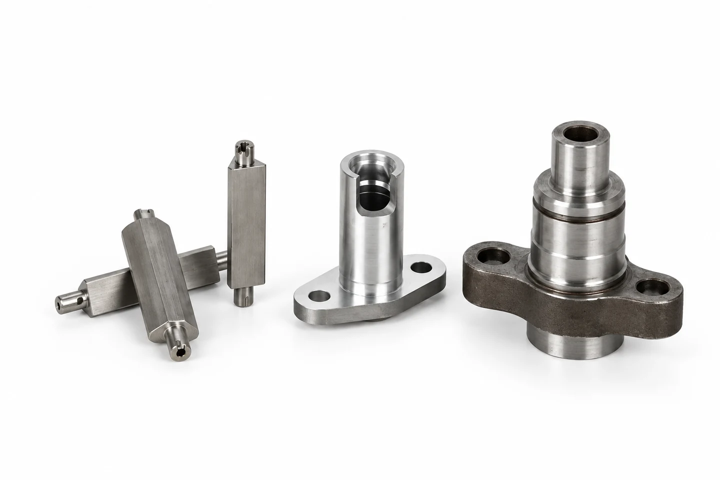
The next image combines turned cylindrical surfaces with flange holes, flats and a side opening. These features raise a different process question from a plain sleeve: which operations require the workpiece to rotate, and which need a powered cutting tool approaching a stationary or indexed feature? GDM-CX46D is a candidate for this work and its published description includes turning, milling, drilling and tapping for short and chucking parts. It therefore belongs in the initial turn-mill comparison. Still review the proposed tooling, approach direction, flange clearance and workholding. The outline of a flange may come from the blank or need another operation. A turn-mill label does not, on its own, establish access to every face or completion of the entire part in one setup.
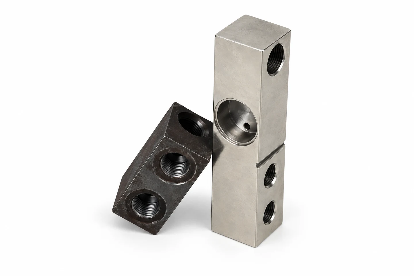
5. Multi-port blocks: fixturing comes before the machine name
The rectangular blocks show several bores and threaded ports, including features on different faces. Their application cannot be determined from appearance alone, so they are described here as multi-port machined blocks rather than a particular customer’s valve or manifold. GDM-CX46D provides a starting point for a fixture and operation review. Establish a suitable setup before proposing it for rectangular stock. Ask which surfaces locate the block, how it is balanced and retained, which holes intersect, and where tools enter and exit. Confirm whether the proposed configuration reaches the required faces or whether regripping or a separate machine is needed. Carry the hole-position, thread and intersection-deburring requirements into the technical review.
6. Threaded connectors and wrench flats: split the process
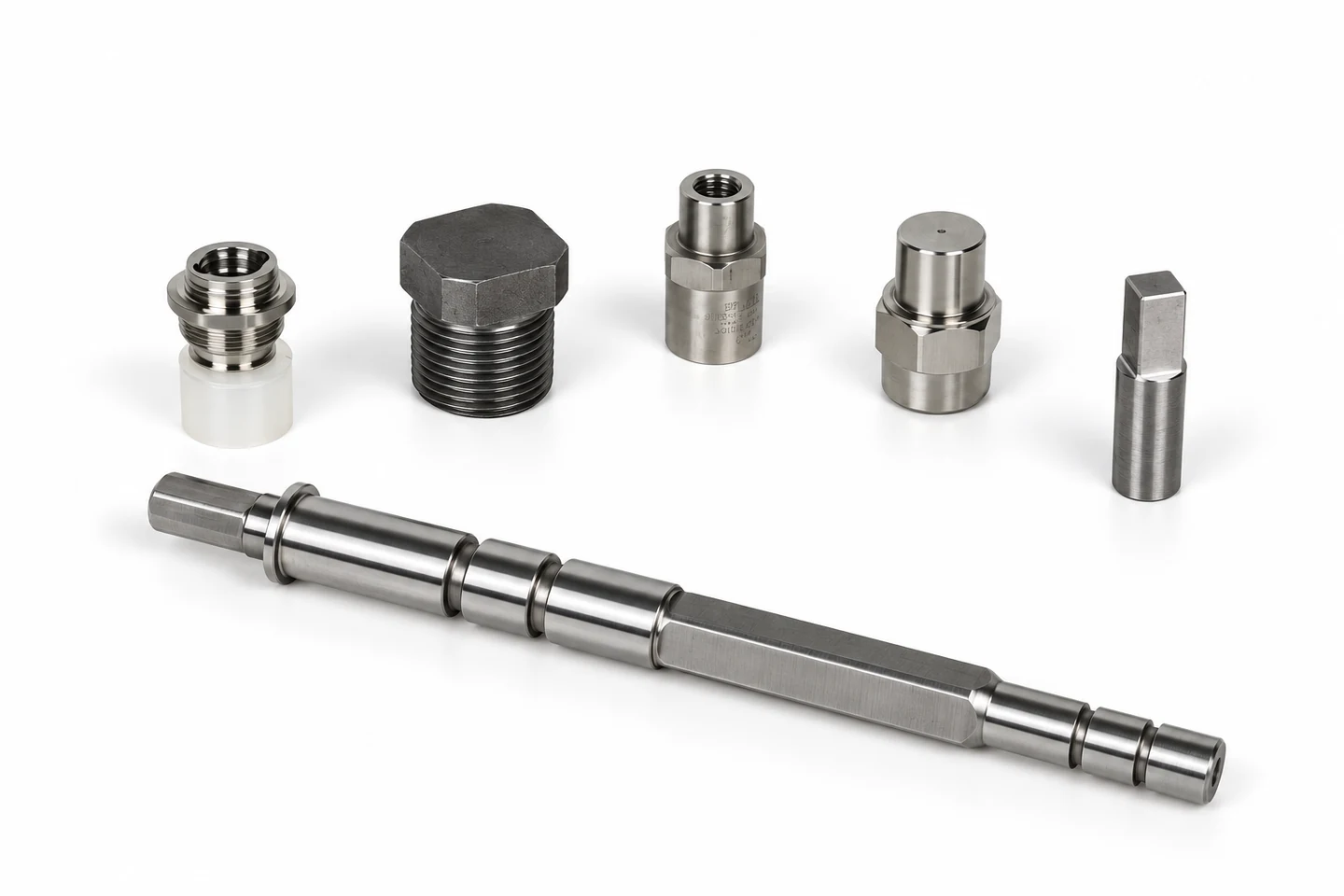
This group includes threaded connector shapes, a hex-head plug and a stepped shaft with a long flat section. GDM-T40-360 is a starting point for the turned features in this group. Its published scope includes bar-turned bushings, pins, connectors, sleeves and threaded parts. That makes it a turning discussion point, while the hexagon, square end or long flat needs a separate explanation of the stock form and cutting route. Do not infer live tooling or a tailstock from the part image. For each non-round feature, state whether it already exists on the blank, is made in a separate operation, or is included in a proposed combined process. Specify the thread form and tolerance from the drawing instead of identifying them from retouched thread detail.
7. Compare part features with the published machine range
Use the table as a shortlist for a drawing review. The model links lead to complete published specifications and the matching images on each product page. These associations follow the supplied examples; they are not an exclusive classification or a promise that the pictured parts fit without changes. Check the actual blank size, finished envelope, gripping allowance, tool clearance and any secondary operations. Published maximum capacity is an initial boundary, not a finished-part guarantee.
| Part family | Starting model | Review before selecting |
|---|---|---|
| Small sleeves, rings and discs | GDM-T40-360B | Bore, wall thickness, gripping and any hex-flat operation |
| Shafts and stepped chucking parts | GDM-T80-350W | Cutting length, projection, support and non-round ends |
| Flanged parts, slots and multi-port blocks | GDM-CX46D | Fixtures, tool approach, face access and separate operations |
| Threaded connectors and bar-turned parts | GDM-T40-360 | Thread specification and the process for wrench flats |
8. Send a drawing that separates each operation
Send Us Your Drawing. Include material grade and condition, blank form and dimensions, quantity, critical dimensions, permitted gripping areas, threads, flats, cross holes and inspection requirements. Mark any feature already present on the blank and any treatment or finishing step outside the machining quotation. This lets the discussion distinguish a turning-only route from turn-mill work or a process using separate machines. For general terminology, Sandvik Coromant explains longitudinal, profile and face turning; its tool guidance is background reading, not evidence of a GEDEMA part trial or supplied tool package. The linked GEDEMA quotation guide helps keep these assumptions visible when comparing proposals.