

Start with the connector body, not the machine label
A small threaded connector body can combine outside diameters, internal bores, shoulders, grooves, threads and sealing faces. It may also include a cross hole, side feature or wrench flat. Mark every feature that is not part of the basic turned profile. This gives the process discussion a useful starting point before choosing between a turret or gang-tool layout.
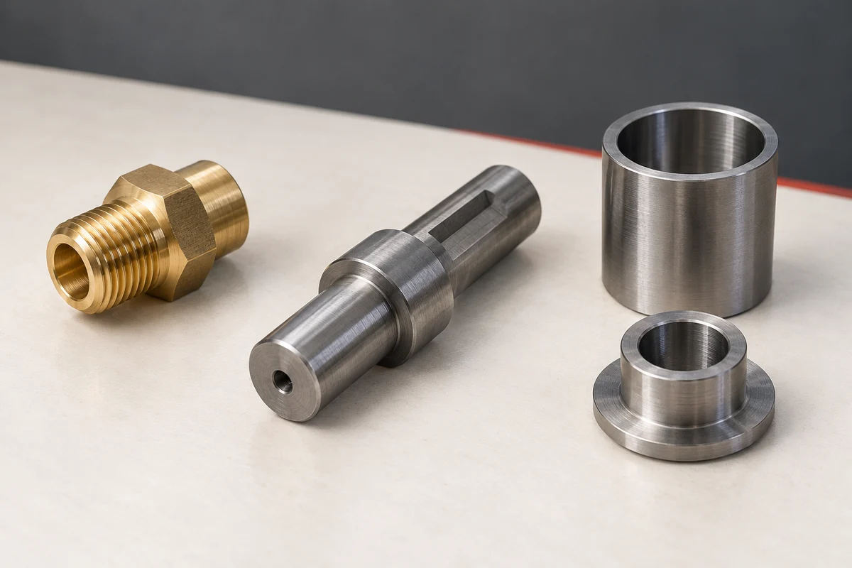
Document stock, thread and cut-off information
Provide the material, stock form, maximum stock diameter, finished length, thread standard and tolerance. Show the bore, sealing feature, groove and cut-off position with their dimensions and datums. These details help frame the tooling and workholding discussion without assuming that all connector bodies use the same machining route.
Gang tool CNC lathe vs turret: compare the actual tool layout
A gang-tool CNC lathe places several tools directly on the slide, with axis movement bringing each tool into the cut. A turret selects tools by indexing stations. For a repeat threaded sleeve, list the facing, OD turning, boring, threading and cut-off tools before choosing the layout. Check boring-bar length, neighboring tool interference and the space left by the chuck or collet. Gang tooling can be a useful starting point for a stable small-part family; a turret is worth comparing when the tool set or part mix changes. Neither layout is automatically faster or cheaper. Compare the complete tool plan and changeover requirements on the same representative drawings.
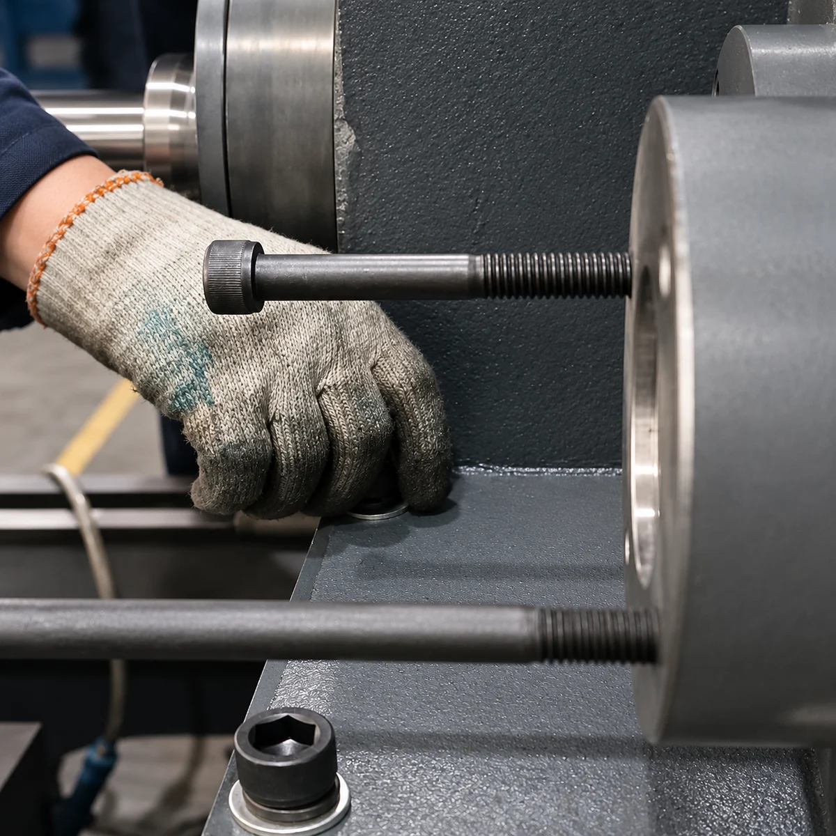
Cross holes and hex flats are separate from the gang-tool decision
Axial drilling and tapping on a turned connector are different from drilling a side port or milling wrench flats. Mark these secondary features before asking for a gang-tool machine quote. GDM-T40-360D offers published turret or gang-tool choices for compact turning work; do not assume that choosing its turret adds live tooling. Use the hydraulic-fitting guide for cross-hole and turn-mill requirements, and the fastener guide for polygon or hex-flat machining. Where a separate setup remains necessary, include its workholding and inspection in the comparison.

Use part variation to structure the tooling discussion
For a family of connector bodies, compare the smallest and largest representative drawings. Identify which features repeat and which change between part numbers, including thread forms, bore depths and secondary features. The drawing review can then consider tool clearance, sequence and access from the real part family rather than from a generic “connector lathe” description.
Where GDM-T40-360D can enter the comparison
For small connector bodies dominated by turning, drilling and tapping, GDM-T40-360D is a compact slant-bed CNC lathe available with turret or gang-tool configurations. Its published range includes a maximum machining diameter of 150 mm, machining length of 320 mm and bar capacity up to 40 mm. These figures are a starting point for comparing a drawing, not a configuration guarantee. Cross holes, wrench flats, non-concentric features, thread length and inspection requirements still need review from the drawing.
Send Us Your Drawing.
Send Us Your Drawing with the material, quantity, critical dimensions, stock form, thread specification, bore and sealing details, secondary features and inspection method. GEDEMA can then compare the part family with published machine specifications without making assumptions from a generic connector description.